A 3D scan captures geometry.
But manufacturing requires intent.
What happens after a 3D scan determines whether that geometry becomes usable—or not.
If you’ve already explored the difference between a 3D scan and a CAD model, the next question is: what actually happens after the scan?
The Reality: The Scan Is Just the Starting Point
A common scenario: a client brings in a physical part: no drawings, no CAD, no documentation.
They assume the scan is the solution.
In reality, the scan is just the beginning, because while a scan can capture shape with incredible precision, it doesn’t automatically produce something that can be modified, manufactured, or integrated into a real-world system.
That gap is where most projects succeed—or fail.
What a 3D Scan Actually Produces
A 3D scan typically outputs one of the following:
- Point cloud — a dense set of spatial data points
- Mesh (STL or OBJ) — a triangulated surface representation
- Textured model — geometry with color information
These formats are excellent at capturing form but they do not include:
- parametric structure
- design intent
- editable features
That distinction is important.
A scan tells you what something looks like.
It does not tell you how it works or how it should be built.
Table of Contents
Step 1: Data Enhancement (Cleaning the Scan)
Raw scan data is rarely usable as-is.
Common issues include:
- noise and artifacts
- incomplete surfaces (holes)
- misalignment between scan passes
- excessive mesh density
This stage involves
- aligning multiple scans
- removing noise
- filling gaps
- simplifying geometry while preserving accuracy
Bad input data guarantees bad output geometry. This is one of the most overlooked—and most important—steps in the entire workflow. The practical implications of different accuracy levels — and what specifications like ±0.03mm actually mean in real conditions — are covered in our guide to 3D scanning accuracy and resolution.
Step 2: Mesh Optimization
Once cleaned, the mesh must be made usable.
That means:
- creating a watertight mesh
- correcting topology issues
- reducing unnecessary polygon density
- ensuring consistent surface quality
At this stage, the model may be usable for:
- visualization
- reference geometry
- certain types of 3D printing
But for most production workflows, this still isn’t enough.
Step 3: Scan-to-CAD (When Needed)
If the goal is manufacturing, modification, or integration into assemblies, the scan must often be converted into a CAD model.
This process, known as scan-to-CAD, involves:
- reconstructing surfaces
- defining parametric features
- rebuilding geometry with design intent
This allows you to:
- adjust dimensions
- apply tolerances
- integrate with other components
- prepare for CNC or production workflows
This is where geometry becomes intent. Not every project requires scan-to-CAD. But when it does, skipping this step guarantees problems downstream.
Step 4: Preparing for Manufacturing
Once you have usable geometry (mesh or CAD), the next step is preparing it for production.
This includes:
- selecting the appropriate manufacturing method
- defining tolerances
- choosing materials
- exporting the correct file formats (often STEP or other CAD formats)
At this stage, the model transitions from digital representation → production-ready asset
Step 5: Build (Physical Output)
The final step is fabrication.
Depending on the project, this could involve:
- additive manufacturing (3D printing)
- subtractive processes (CNC machining)
- casting workflows
The key point: The quality of the final part is directly tied to how well each previous step was executed.
When Can You Use a Scan Directly?
There are cases where scan data can be used without full reconstruction:
- organic or sculptural objects
- visual prototypes
- low-tolerance 3D printed parts
However, for most functional or production applications, additional processing is required.
Why This Workflow Matters
Many issues attributed to “bad scans” are actually workflow failures.
Common problems:
- assuming a mesh is manufacturing-ready
- skipping scan-to-CAD when it’s needed
- ignoring tolerances
- using the wrong fabrication method
Understanding what happens after the scan helps avoid:
- costly rework
- poor fit or performance
- delays in production
From Capture to Production: An Integrated Approach
At Kemperle Industries, we approach 3D scanning as part of a larger system:
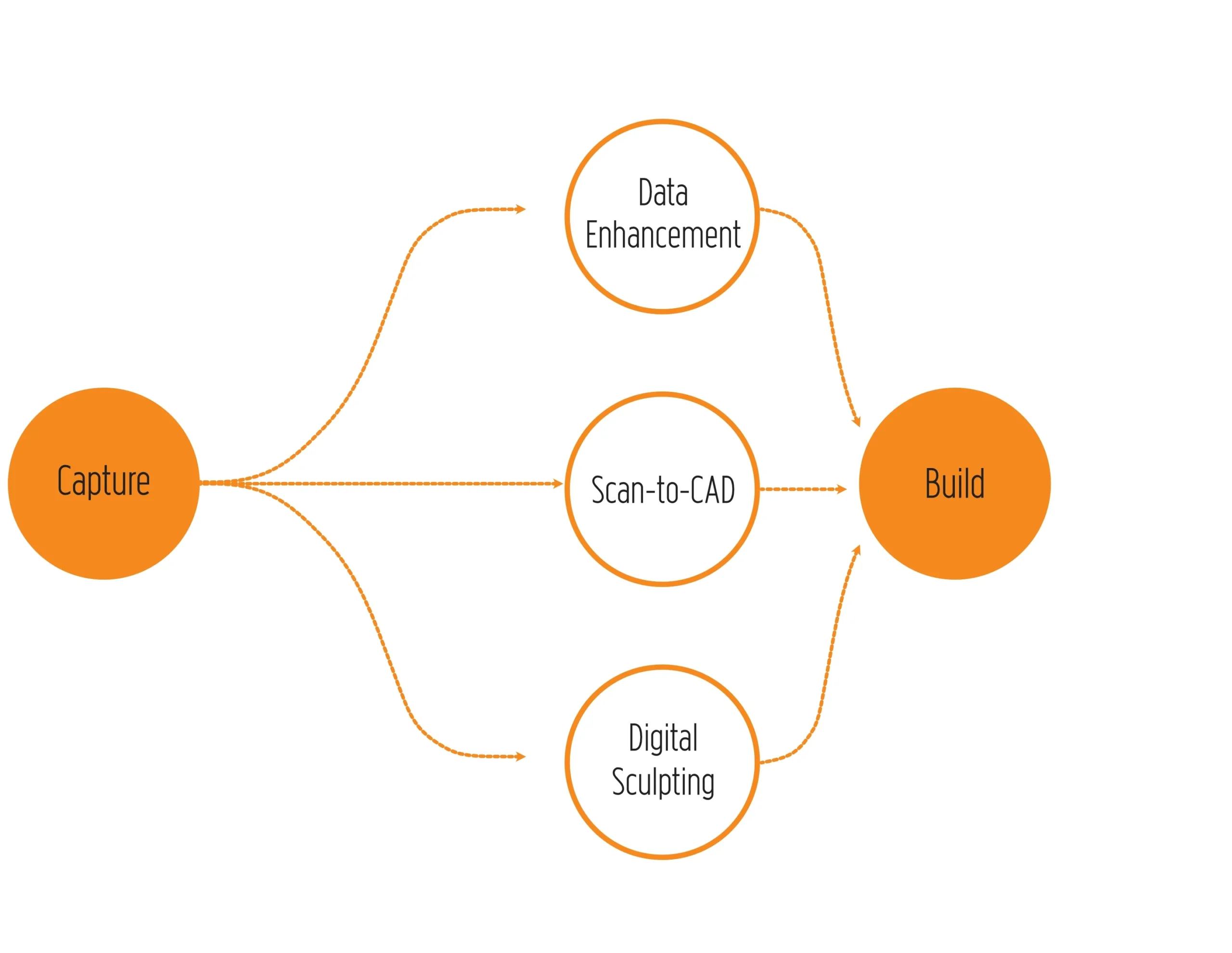
The goal isn’t just to digitize objects. It’s to create geometry that can be:
- modified
- manufactured
- installed
- trusted in real-world conditions
If you’re working from existing parts, legacy components, or complex geometry, understanding the full workflow can make the difference between a model that looks right and one that actually works.
Learn more about our 3D scanning and reverse engineering services →
Frequently Asked Questions
Can you manufacture directly from a 3D scan?
Sometimes. But most production workflows require additional processing or CAD conversion.
What is scan-to-CAD?
Scan-to-CAD is the process of converting mesh data into a parametric, editable model suitable for engineering and manufacturing.u003cbru003eu003cbru003eu003ca href=u0022https://kemperleindustries.com/3d-scan-vs-cad-model/u0022u003e3D Scan vs CAD model: Why they’re not the same (and why it matters for manufacturing)u003c/au003e
What file format do manufacturers need?
Most manufacturing workflows require CAD formats such as STEP, rather than raw mesh files like STL.